|
|
Nixietach II
Introduction
Nixietach II is a deluxe electronic tachometer built for my 1971 Ford LTD. Discretely mounted along the bottom of the vehicle's dashboard, Nixietach II reports revolutions per minute (RPM) with a quantization error of only 0.03 RPM at 1,000 RPM. Flipping a switch allows the design to double as a precision dwell meter. Either measurement is shown on the design's lustrous cold-cathode display, built from authentic Soviet-era Nixie tubes. A rear-facing USB port allows for logging data to a file and exposes a command-line interface for control of the device. The design supports four, six and eight cylinder engines and is enclosed in a sumptuous anodized aluminum frame with ABS plastic insets.
Its most practical feature, however, is its Bluetooth LE interface for streaming data to a mobile device in real time. Live RPM and dwell readings are reported to a mobile app developed by Adafruit, turning your phone into a wireless tachometer for easy tune-up work under the hood.
A brief video of the design's display changing as the accelerator is moved can be seen on YouTube. The project was featured on both Hackaday and Hackster, as well as the Adafruit blog.
Photos
|
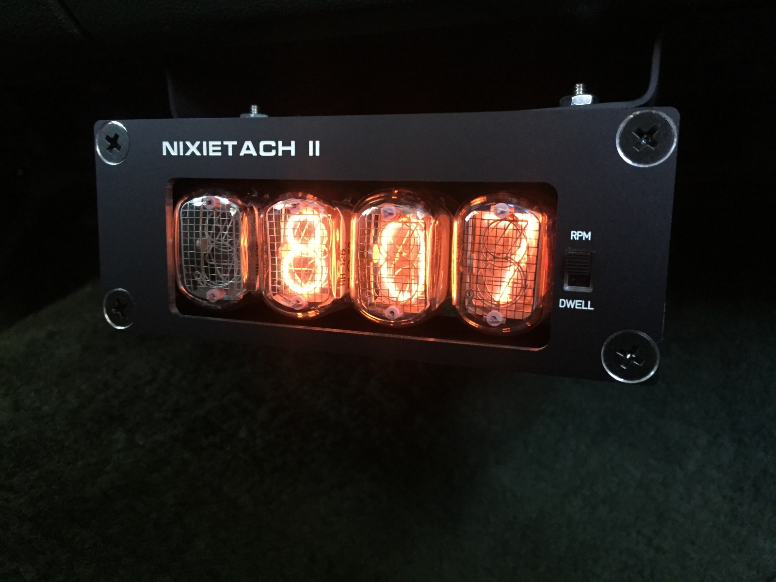
Figure 1: Close-up of display.
|

Figure 2: Back view.
|
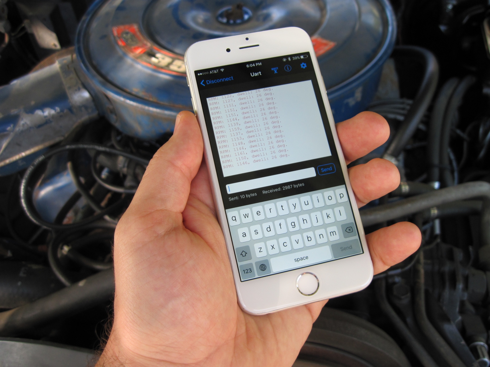
Figure 3: Mobile app with live data stream.
|
History and Motivation
The idea of making a digital tachometer started in 2008 while I was a graduate student. It was not until 2012 that I put the idea into practice, which I called Digitach and installed in my 1979 Ford F100 pickup. That design leveraged the input capture channel of a microcontroller to calculate RPM based on the switching frequency recovered from the vehicle's ignition coil, and would form the basis for future projects. Although Digitach saw several years of use, it was highly unsightly and lackluster. Since it was my first real project outside of a professional setting, I was just happy to have a working board and forwent any sort of industrial design.
One year later, I set out to create another digital tachometer—this time with antique Nixie tubes and an enclosure. The result was Nixietach, and it featured a beautiful vintage display nestled inside an anodized aluminum housing. While that project was a step in the right direction, it suffered from two flaws—first, aside from the lively presentation of RPM, Nixietach lacked any exciting features and was largely an exercise in repetition. Second, its industrial design was entirely an afterthought. Since I freely designed the electronics without any spatial constraints up front, Nixietach wound up too large to actually install.
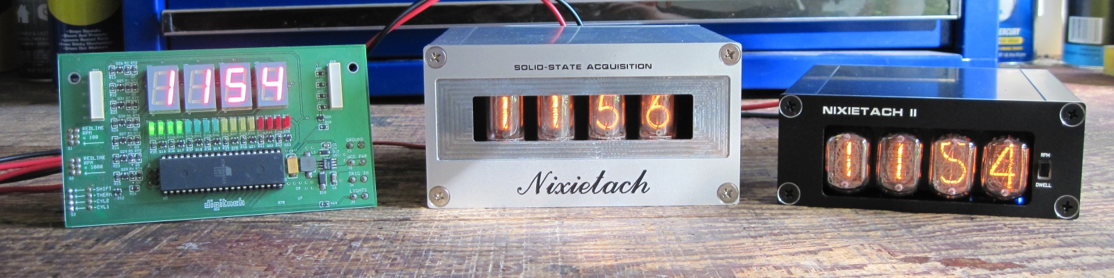
Figure 4: From left to right: Digitach, Nixietach and Nixietach II.
Another challenge common to both projects was the method by which they recovered the coil's switching frequency. Both designs used a separate trigger box that resided in the vehicle's engine bay. The trigger box physically intercepted the wiring to the vehicle's ignition coil to measure the current through its primary winding—making either tachometer difficult to install. Furthermore, the measurement method could retain the current's frequency, but not its duty cycle. As I'll explain later, duty cycle translates to dwell angle—which neither Digitach nor Nixietach could report.
By 2017, the truck had been sold and the original Digitach was tucked away in storage. With my work no longer on display, I decided to build another design that addressed all of the lessons I had learned. This time, I set three goals: the design must be self-contained and easy to install, the enclosure must be of reasonable size, and the project needs to feature some new and exciting design elements. With these goals in mind, Nixietach II was born.
Theory of Operation
Automotive ignition systems generally fall into one of two categories—inductive discharge and capacitive discharge. In the far more common inductive-discharge system, the primary winding of an autotransformer, or ignition coil, is rapidly charged and discharged with a switch. As I detail further in the documentation for Digitach and its companion trigger box, RPM is proportional to the frequency at which the switch is opened and closed. The length of time the switch is closed relative to the entire switching period, or duty cycle, is called the dwell angle and is a meaningful adjustment for various ignition system implementations (more on that later).
Whether the switch is open or closed is apparent in the voltage across the switch, or vswitch. Because the switch connects to ground, vswitch is zero while the switch is closed and current through the primary winding of the ignition coil exponentially increases. When the switch opens, vswitch rapidly increases to hundreds of volts as the current is abruptly stopped. Next, vswitch oscillates briefly before settling to the vehicle's battery voltage, where it remains until the switch is closed for the next switching cycle. Figure 5 below shows a typical period of vswitch.
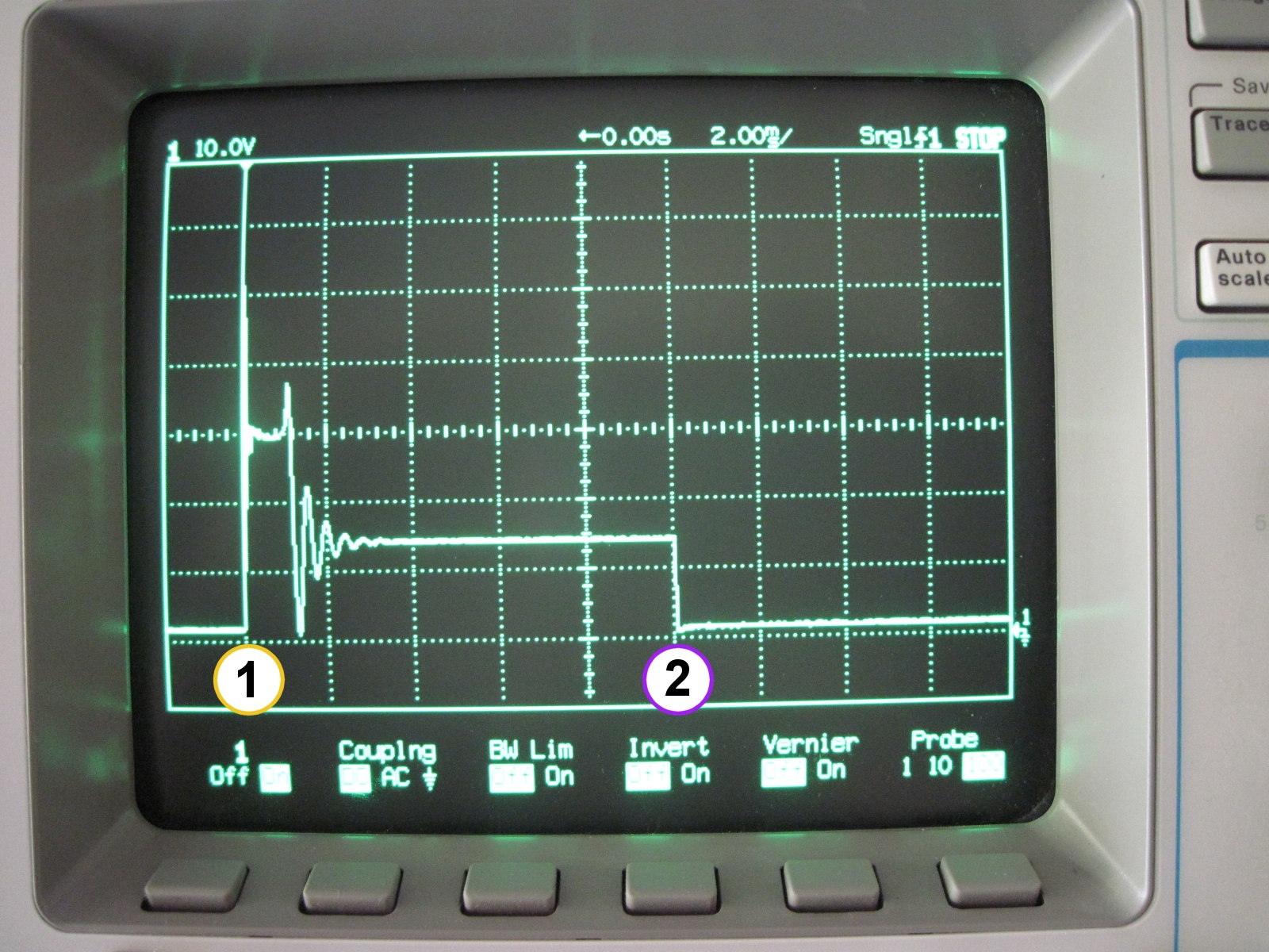
Figure 5: Typical period of vswitch as the switch opens (1) and closes (2).
Conveniently, vswitch is easily accessible on most engines because it is often exposed as a terminal on the vehicle's ignition coil. Nixietach II satisfies its requirement to be self-contained and easy to install by making a nonintrusive connection to this terminal. The challenge, however, is to condition vswitch into a logic-level signal from which a microcontroller can recover frequency and duty cycle to report RPM and dwell angle, respectively.
Signal Conditioning
Based on its voltage level, vswitch can be mapped to a binary representation of switch state, which we'll call vtach. While vswitch is equal to zero, the switch is presumed closed and vtach is logic-high (the actual polarity is arbitrary). During all other times—whether vswitch is climbing to hundreds of volts, oscillating, or resting at the vehicle's battery voltage—the switch is presumed open and vtach must be of opposite polarity (logic-low in this case).
In practice, however, vswitch crosses zero several times even while the switch is open. These transitions are the result of resonance created between the inductance of the ignition coil's primary winding and any capacitance in parallel with the switch. Therefore, a signal-conditioning circuit must decipher whether vswitch is equal to zero because the switch is actually closed, or because vswitch is simply oscillating. The circuit must also withstand the hundreds of volts seen on vswitch when the switched is opened. Figure 6 below depicts a circuit that satisfies both requirements.
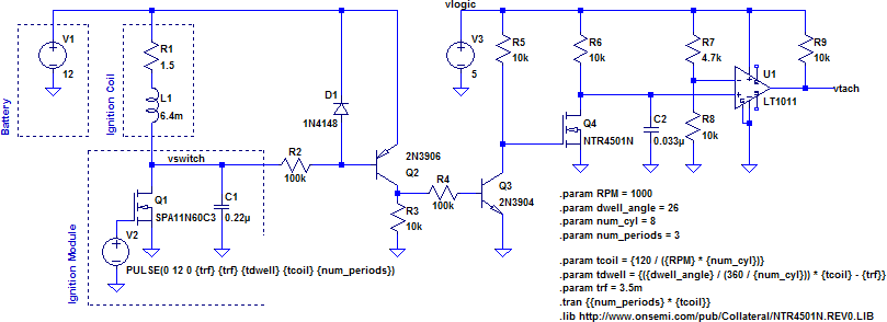
Figure 6: Circuit for conditioning vswitch into a logic-level signal.
R1 and L1 model the primary winding of an ignition coil; the component values come from a real-world example. Q1 represents the ignition module switch, with vswitch shown as Q1's drain-to-source voltage. When the switch is closed, current is drawn from the base of Q2, forcing Q2 to conduct. Turning on Q2 also turns on Q3, which subsequently turns off Q4. With Q4 off, C2 charges to vlogic through R6. Once the voltage across C2 exceeds the threshold created between R7 and R8, the comparator output is asserted. After the switch is opened and vswitch rapidly increases, Q2 and Q3 immediately shut off. Q4 subsequently turns on, discharging C2 and reversing the polarity of the comparator output as shown in Figure 7.
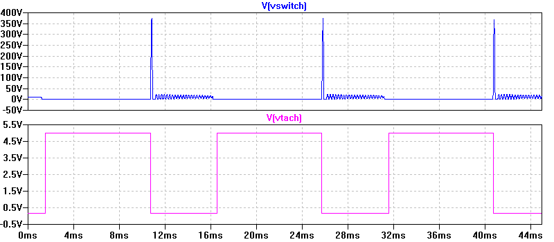
Figure 7: LTspice simulation showing vswitch and vtach.
It is the time constant between R6 and C2, coupled with the divider between R7 and R8 that is responsible for rejecting spurious zero-crossings as vswitch oscillates following the opening of the switch. Assuming nominal component values, Q2 must conduct for at least 410 μs for vtach to be asserted—sufficiently beyond the resonant period of most ignition systems. This "debounce" delay does in fact skew the duty cycle recovered from vswitch—but because the delay is known, it can be accounted for as part of the microcontroller's calculation of dwell angle. Component tolerance and comparator input offset introduce a small error that cannot be compensated, but in practice the error is insignificant because dwell angle is relatively coarse in the first place.
Lastly, D1 in Figure 6 serves to limit the emitter-base breakdown voltage of Q2 when the switch opens and vswitch peaks at hundreds of volts. The forward voltage of D1 (approximately 0.7 V) is well below the maximum emitter-base breakdown voltage of Q2 (5.0 V). I tested the circuit by building the prototype shown in Figures 8 and 9 below, installed in a similar location as the finished product. Figure 10 shows that the prototype behaves exactly as predicted by the simulation shown in Figure 7 above.
|
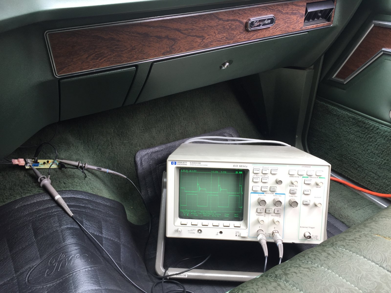
Figure 8: Prototype on floorboard of vehicle.
|
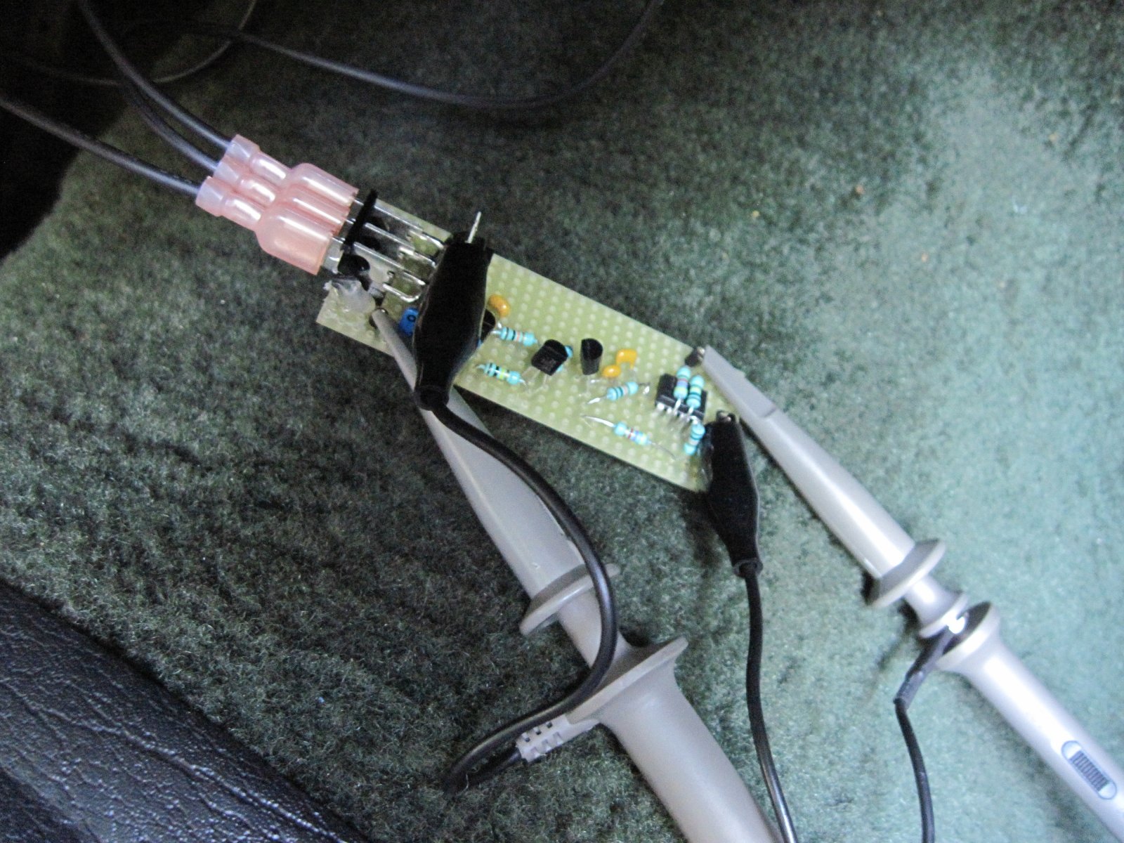
Figure 9: Close-up of prototype.
|
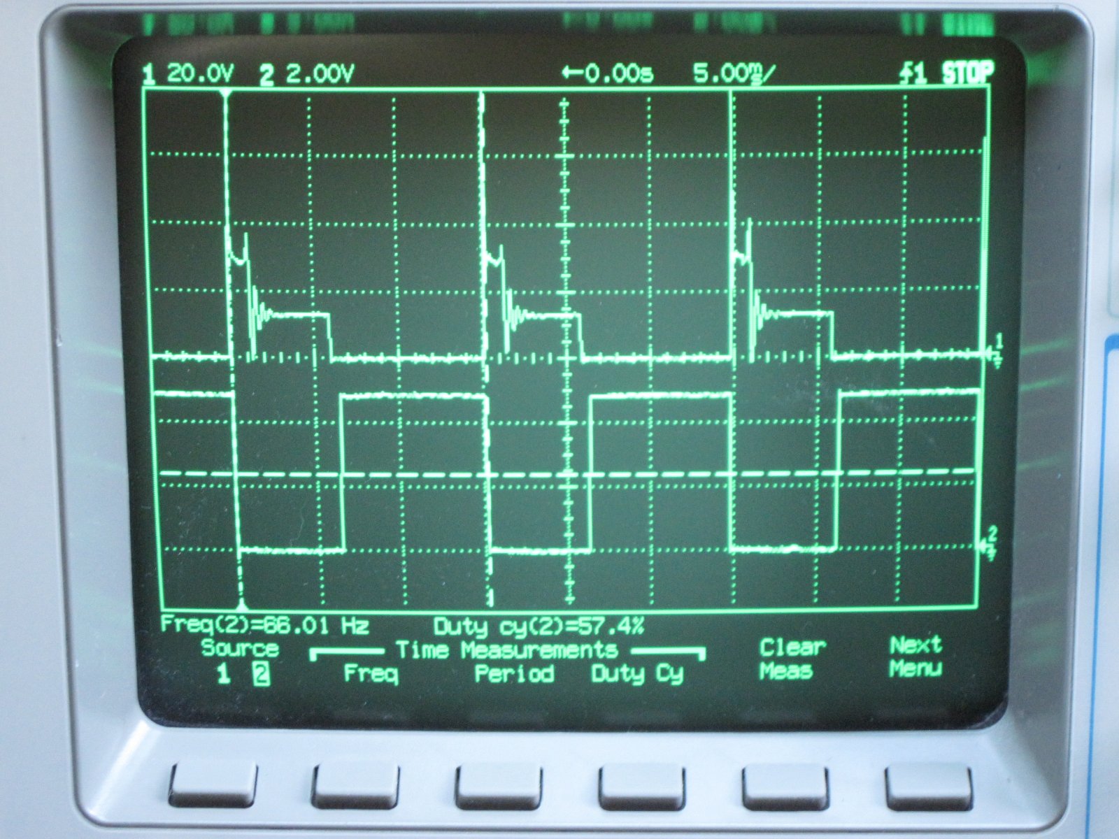
Figure 10: Oscilloscope capture showing vswitch (channel 1 at top) and vtach (channel 2 at bottom).
|
|
For a future revision, I would consider tying the emitter of Q2 and the cathode of D1 to vlogic instead of the vehicle's 12-volt supply. This small modification would protect against noise that could mistakenly enable Q2 and corrupt vtach. The microcontroller performs enough filtering, however, that the present design is sufficiently robust under typical driving conditions.
Measuring Time
The input capture channel of a microcontroller can measure the positive and negative pulse widths of vtach to derive the frequency and duty cycle of vswitch—yielding RPM and dwell angle, respectively. By connecting vtach to a dedicated pin of the microcontroller, positive or negative edges along vtach force the microcontroller to store the value of a free-running counter and signal an interrupt. An interrupt service routine (ISR) subsequently resets the counter, arms the input capture channel for the next edge and signals that a new pulse width is available for analysis. Figure 11 shows a conceptual drawing of the ISR.
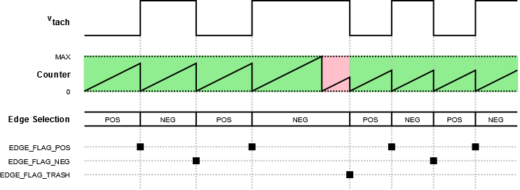
Figure 11: Input capture ISR diagram.
An input capture channel can be configured as sensitive to positive or negative edges, but seldom both at the same time. Reacting to a single polarity can capture vtach's entire period, but not its duty cycle. By inverting the polarity selection within the ISR, however, both frequency and duty cycle can be reported because positive and negative pulse widths are captured separately. The ISR can determine the polarity of each recently completed pulse based on the edge selection at the time the ISR is entered.
The ISR sets a global flag to indicate that a valid pulse width is available in the input capture register for processing; the value of the flag indicates the pulse's polarity. The flag is set to EDGE_FLAG_NEG to indicate that a negative edge has terminated a positive pulse width; conversely, the flag is set to EDGE_FLAG_POS to indicate that a positive edge has terminated a negative pulse width. After the microcontroller's main loop queries the input capture register, the flag is reset.
To handle long pulse widths that force the counter to wrap around, the input capture ISR checks the corresponding overflow interrupt. If the overflow interrupt was found to be asserted since the last edge, the ISR sets the global flag to EDGE_FLAG_TRASH instead of EDGE_FLAG_POS or EDGE_FLAG_NEG to warn the main loop that the recently completed pulse and its complementary neighbor must be discarded. The ISR then resets the overflow interrupt in preparation for the next edge. The main loop interprets EDGE_FLAG_TRASH to indicate that vtach is too slow to measure or has disappeared, likely because the engine is not running.
One full switching cycle of the ignition coil comprises a positive pulse along vtach followed immediately by a negative pulse—corresponding to the length of time that the switch is closed and then held open, respectively. A complete cycle is therefore signaled by back-to-back EDGE_FLAG_NEG and EDGE_FLAG_POS flags, in that order. The microcontroller's main loop proceeds to determine the coil's instantaneous frequency and duty cycle, calculated as follows:
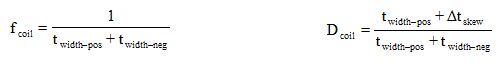
Where:
- fcoil = coil switching frequency, measured in Hz
- Dcoil = coil duty cycle, expressed as a ratio between zero and unity (inclusive)
- twidth–pos = vtach positive pulse width, measured in seconds
- twidth–neg = vtach negative pulse width, measured in seconds
- Δtskew = difference between twidth–pos and the actual time the switch is closed, equal to 410 μs (based on the delay described under Figure 7)
Calculating RPM based on fcoil is discussed throughout the documentation for Digitach, so I won't rehash it here. Dwell angle, however, is seldom explained in detail and warrants further discussion.
Dwell Angle
The duty cycle of an ignition coil refers to the percentage of the coil's switching period that is reserved for charging the coil's primary winding. Duty cycle is controlled by a switch that selectively gates current through the primary winding. If the switch were permanently held open, the duty cycle would equal zero; conversely, if the switch were permanently held closed, the duty cycle would equal unity (and the ignition coil would likely overheat). Realistically, neither scenario would make for a running engine and duty cycle is typically between 50% and 70%.
In the automotive world, the term "duty cycle" is seldom used and the measurement is instead referred to as dwell angle or simply dwell. Dwell angle is critical because of two conflicting requirements—the switch must remain closed long enough to build sufficient current through the coil's primary winding, but it must be held open long enough for the magnetic field to collapse as a spark is generated from the coil's secondary winding. This is especially important at high RPM for which the switching cycle can be as short as 2 ms.
Dwell is expressed as an angle because of the mechanism originally used to open and close the switch. Prior to the 1970s, a mechanical switch was positioned in the vehicle's distributor, actuated by a small cam fixed to the distributor shaft. As the shaft rotated, the normally closed switch was momentarily opened by ridges that were spaced evenly along the circumference of the cam. With the number of ridges equal to the number of cylinders in the engine, each cylinder was mapped to an equivalent angle of rotation within which an entire coil switching cycle was completed.
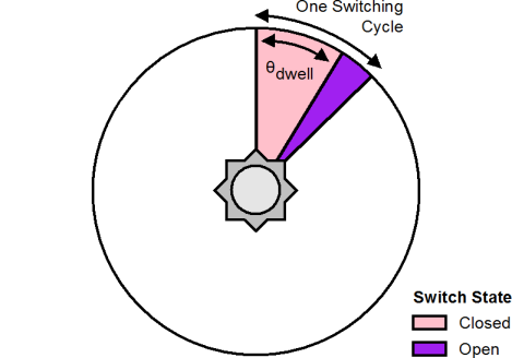
Figure 12: Conceptual drawing of distributor with cam in the center, seen from above (8-cylinder example).
Each of these four, six or eight "slices" was divided into two angles—the angle for which the switch remained closed, and the angle for which the switch was held open. The former represents the dwell angle, and is expressed as follows:
θdwell = 360 × Dcoil ÷ n
Where:
- θdwell = dwell angle, measured in degrees
- Dcoil = coil duty cycle (explained earlier)
- n = number of cylinders (4, 6, or 8)
The mechanical switch was referred to as a set of "breaker points," and the dwell angle was controlled by physically adjusting the distance between the switch contacts while the switch was held open by the cam. A shorter distance represented a larger dwell angle, and vice versa. This process was called "gapping the points" and was performed with a feeler gauge. With breaker points having been replaced by modern electronic ignition, dwell angle is controlled electronically and requires no manual adjustment.
Figure 11 suggests that the maximum pulse width that can be measured is limited by the counter's ceiling. Since one full switching cycle comprises both a positive and negative pulse along vtach, the tachometer's measurement range is maximized when the pulses are equal in width, corresponding to a duty cycle of 50%. In practice, however, duty cycle varies across applications and one pulse is wider than its counterpart—forcing the maximum period that can be measured to be limited by the wider of the two complementary pulses. The minimum fcoil and therefore minimum RPM that can be measured are dependent on dwell angle as Figure 13 shows.
Figure 13: Minimum RPM vs. dwell angle.
Each plot in Figure 13 is generated by sweeping duty cycle from 20% to 80%—covering a wider range of dwell angle as the number of cylinders is reduced. The vertex of each plot represents 50% duty cycle, with the tachometer's range shrinking as dwell angle moves from this point. The 1971 Ford shop manual specifies 24°–29° for my LTD's 8-cylinder engine. I find that the Pertronix Ignitor module I've installed in the vehicle holds the dwell angle at a steady 26°—meaning I can expect to measure as low as 266 RPM. Conversely, a 4-cylinder Ford Pinto with a dwell angle of 40° can be measured down to 513 RPM—sufficient to capture either vehicle's idle speed.
Display Design
After completing the original Nixietach project, I concluded that vertical indicator tubes do not make for an efficient use of space, especially when standing in a socket. Their construction makes for a rather narrow viewing area within a relatively large faceplate. Instead, those tubes are much better suited for modern clock designs like the beautiful Zen Nixie Clock from the incredibly talented Dalibor Farny. In that example, the entire tube is exposed to enhance the design's unique look.
Nixietach II's second requirement was to fit inside a reasonably sized enclosure—to that end, I decided that horizontal Nixies would minimize the amount of unused space on the front of the enclosure and make for a tight, compact design. I chose the ever-popular Russian IN-12A/IN-12B tube because of its comfortable digit height and wide availability.
|
Figure 14: Illuminated IN-12A tube.
|
Figure 15: Side profile of IN-12B tube (the "B" model adds a decimal point). Note the CCCP insignia and 1980 date code.
|

Figure 16: Four IN-12B tubes arranged on the display board with tester assembly above.
|
|
The consequence of using horizontal indicator tubes is that they must be supported by a separate display board mounted perpendicular to the design's main board. The display board, shown in Figure 16 above, adds cost to the project. The other device in Figure 16 is a convenient Nixie tube tester from Romania. The tester is fitted with an IN-12A/IN-12B socket that allows each element of the tube to be checked prior to soldering the tube to the display board.
The four-digit display is controlled in the same fashion as Nixietach II's predecessor—the microcontroller drives two daisy-chained shift registers that mimic a SPI slave. Each eight-bit shift register fans out to two BCD decoders; each decoder is mapped to one Nixie tube and drives ten high-voltage NPN transistors that sink the tube's individual cathode currents. This scheme reduces 40 control signals down to only three microcontroller outputs at the expense of added logic.
The Nixie tubes are powered by a 180-V boost converter built using the MAX1771 controller. This device is popular among Nixie designs because it features a pulse-skipping mode for increased efficiency at light loads such as Nixie tubes. The boost converter can be selectively enabled or disabled by the microcontroller. Disabling the boost converter simply reduces the output voltage to a diode drop below its input voltage, but in practice this is sufficient to extinguish the display.
USB Interface
The third and final requirement of Nixietach II was to include something new and exciting, which I accomplished by exposing a means to communicate with the design. The rear-facing USB port exposes a command-line interface that can be accessed with a terminal application like PuTTY, shown in Figure 17 below.
Figure 17: Command-line interface as viewed through a terminal application.
The command-line interface interprets the command set defined in the following table:
| Command |
Description |
|
ble <reset|at_cmd>
|
Forces one of the following actions upon the BLE module:
- reset: apply a momentary reset
- at_cmd: send at_cmd as an AT command and return the module's response
ble sent without an argument returns an error.
|
|
cyl
|
Displays the engine's number of cylinders, as selected by the rear-facing cylinder select switch.
|
|
disp <on|off|num|reset>
|
Forces one of the following actions upon the front-facing display:
- on: force the display on
- off: force the display off
- num: print num to the display (for demonstration purposes)
- reset: remove num and return to normal operation
disp sent without an argument returns the display's state (on or off).
|
|
rpm <start>
|
Prints the most recent RPM and dwell readings to the terminal. The optional start argument enables data logging, in which case readings are continuously printed to the terminal at half the rate they are printed to the display. Pressing any key disables data logging.
|
|
ver
|
Displays version information.
|
Nixietach II connects to the USB host as a virtual COM port (VCP) at 19.2 kbps (8-N-1). The VCP is presented by a USB-to-UART converter. There are many converters on the market, but I chose the MCP2200 because it is the only device I found that offers an easy-to-solder SOIC package. Like its competitors, the MCP2200 offers a versatile configuration tool, shown in Figure 18 below.
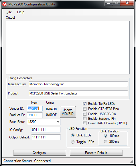
Figure 18: MCP2200 configuration utility.
The MCP2200 directly controls two activity LEDs that are exposed on the rear panel, labeled "talk" and "listen" to signal that the device is transmitting and receiving, respectively. In practice, the "listen" LED is always accompanied by the "talk" LED because any character received through the command-line interface is echoed to the terminal.
Bluetooth LE Interface
The most compelling piece of this project wasn't even part of the original plan—until partway through the design, a close friend asked "why not add Bluetooth?" Initially brushing off the idea as a joke, I soon realized that remote data logging would make the design incredibly useful. Classic-car enthusiasts typically own two tachometers—an aesthetic dash-mounted unit in the form of a large dial for driving, and a second handheld device that is temporarily connected under the hood for stationary tune-up work. Adding a wireless interface to Nixietach II would satisfy both use cases with a single device.
Soon after, I found that Adafruit offers the extremely versatile Bluefruit LE SPI Friend—a compact breakout board that implements a turn-key bridge between Bluetooth LE and a simple-to-use SPI interface. This BLE module, shown in Figure 19 below, connects to a host platform using a nine-pin header and can be powered by a 5-volt or 3.3-volt supply. It offers a four-wire SPI interface, optional interrupt output and optional reset input for connection to a separate microcontroller.
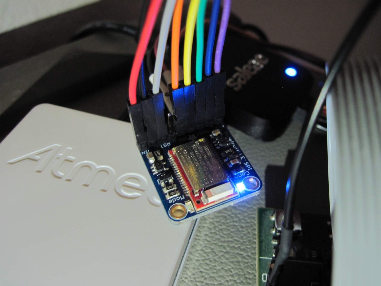
Figure 19: Bluefruit LE SPI Friend fitted with fly-wires to host microcontroller development board and logic analyzer.
The BLE module leverages a simple protocol defined by Adafruit called the Simple Data Exchange Protocol, or SDEP. For the most part, SDEP packets fall into one of two categories—AT command/response pairs or UART exchanges. Figure 20 below shows an example in which the host microcontroller queries the BLE module by sending the AT command, to which the module responds with "OK" a short time later.
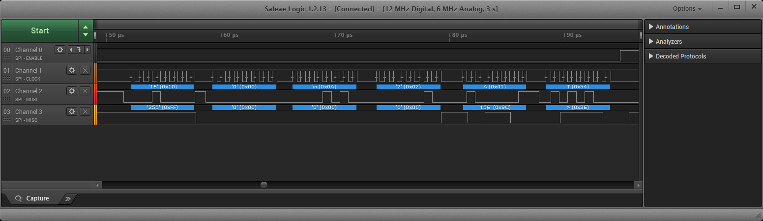
Figure 20: SDEP packet consisting of message type, command ID, length and payload fields.
The contents of SDEP packets carrying the UART designation are shared over the Bluetooth LE link with the UART service of a connected application. This conduit allows arbitrary messages to be sent from a wireless accessory to a mobile app. Messages can also be sent from the same mobile app to the wireless accessory, where they are queued until the accessory polls the BLE module.
I decided to apply this concept to Nixietach II by extending its command-line interface to a BLE-connected mobile app, operating in parallel with the existing USB virtual COM port. Commands entered over USB solicit a response over USB. Responses to those same commands when delivered over Bluetooth LE, however, are presented in the mobile app from which the original command was generated. Adafruit offers an app that includes a terminal, shown in Figure 21 below, that facilitates UART exchanges with the wireless accessory. Commands are entered in the text box to the left of the Send button, and Nixietach II's responses are shown in the window above it.
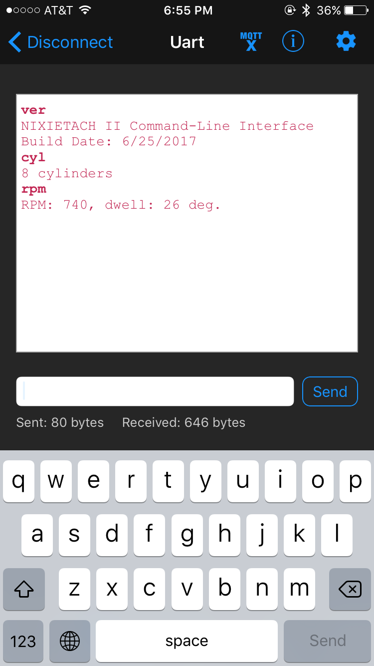
Figure 21: Bluefruit LE SPI Friend companion app from Adafruit.
By taking advantage of Nixietach II's flexible command set, the app transforms the mobile device into a wireless tachometer. Simply sending rpm as in Figure 21 returns the tachometer's instantaneous RPM and dwell readings. Sending rpm start, however, streams live readings continuously just like in Figure 3. This feature is especially useful while adjusting the vehicle's carburetor and watching for changes in idle speed.
There are two changes to the standard command set when exercised over the Bluetooth LE link:
- The ble command is not available through the mobile app. This restriction prevents the user from configuring the BLE module in such a way that it disconnects and cannot be discovered (such as reducing the radio power).
- The rpm command offers the additional stop argument to disable data logging after having been enabled with the rpm start command. Because the mobile app requires messages to be followed by a carriage return, pressing any key to disable data logging as would be done through the USB interface is insufficient.
The Bluefruit LE SPI Friend enabled me to add innovative features to Nixietach II without the burden of developing a Bluetooth LE firmware stack or associated mobile app. Relying on a standalone module helped limit the scope of the project while introducing me to new and exciting technology.
More Photos
|
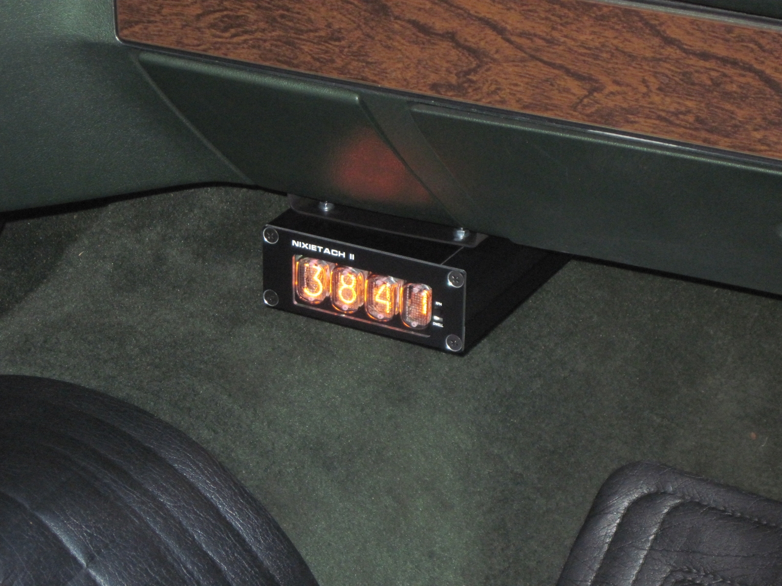
Figure 22: Front view with unit installed under dash.
|
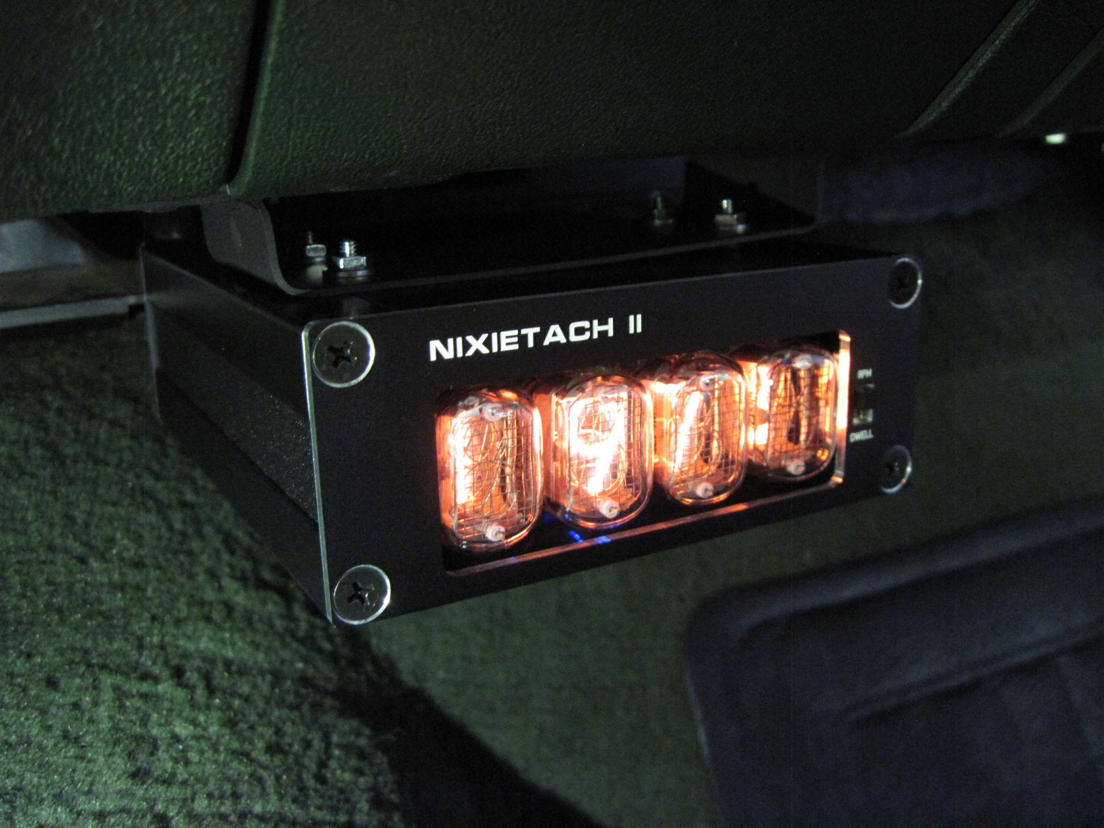
Figure 23: Close-up of installation.
|
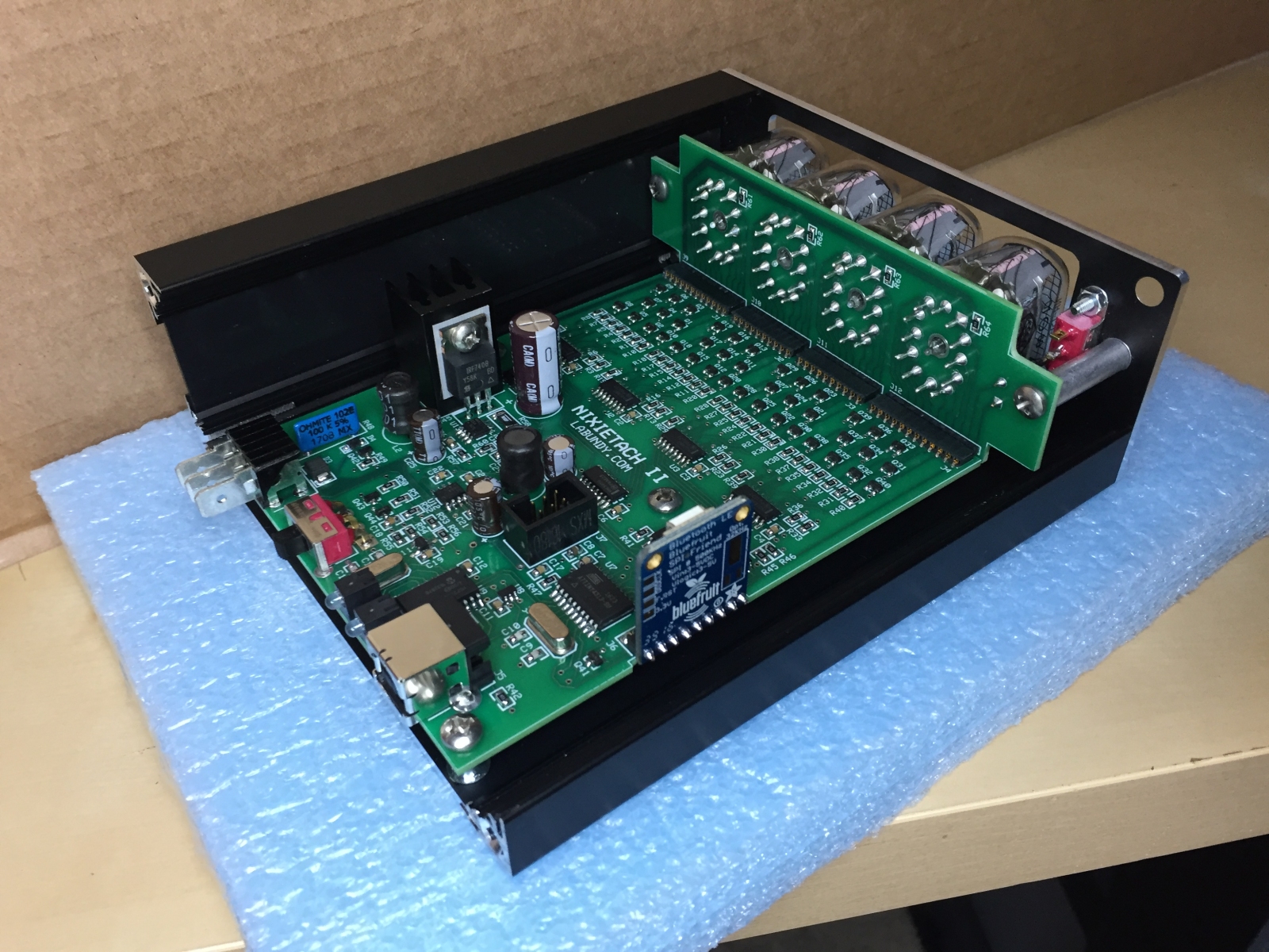
Figure 24: Inside view.
|
Schematic—Main Board
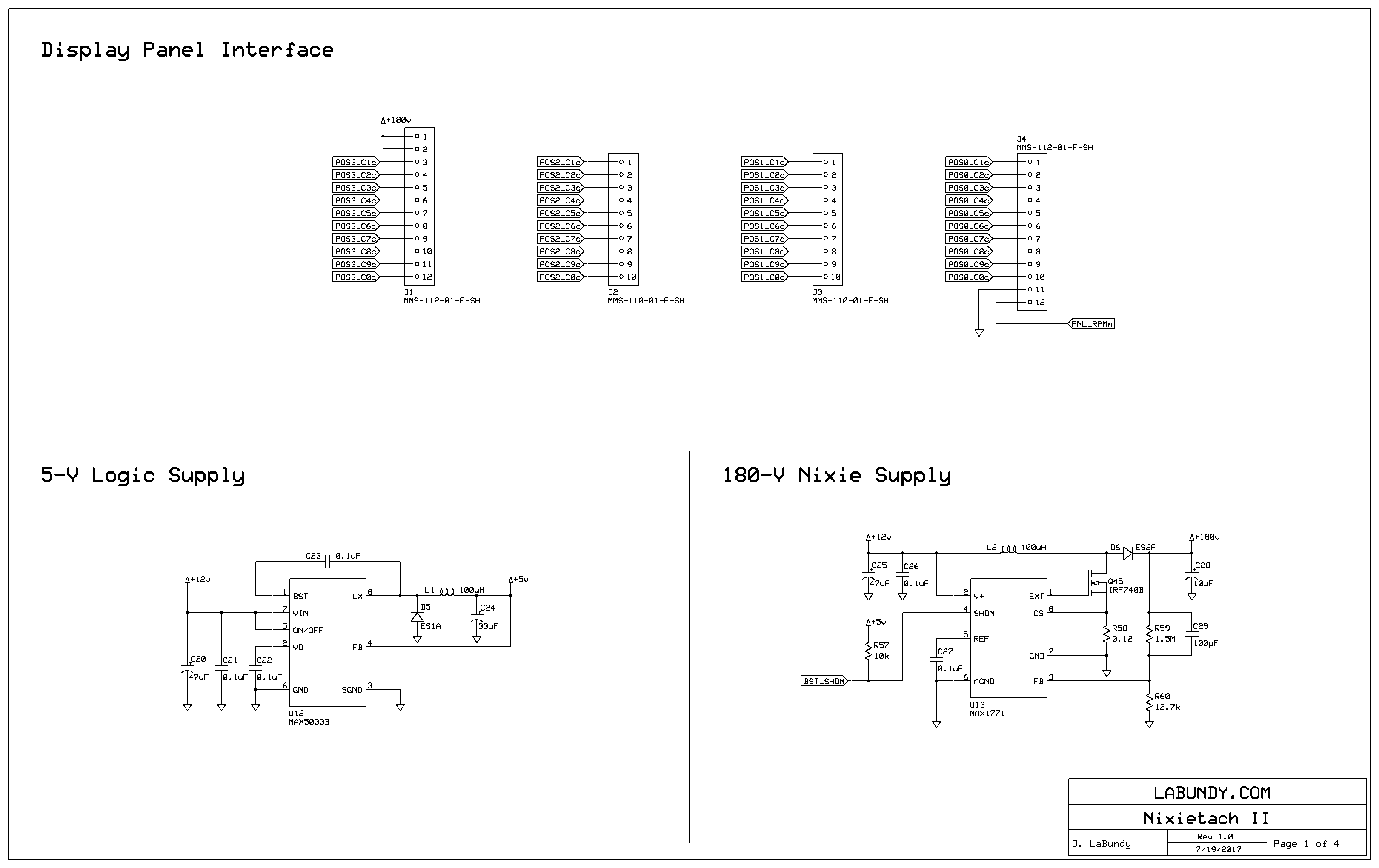
Figure 25: Main board schematic page 1 of 4.
|

Figure 26: Main board schematic page 2 of 4.
|

Figure 27: Main board schematic page 3 of 4.
|
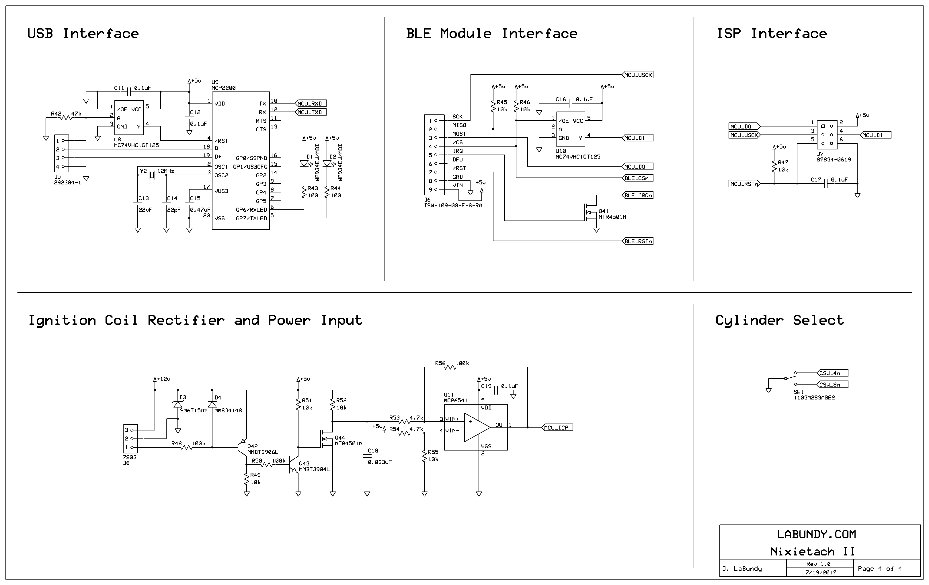
Figure 28: Main board schematic page 4 of 4.
|
Schematic—Display Board

Figure 29: Display board schematic page 1 of 1.
PCB Layout—Main Board
Click here to download in Gerber format.
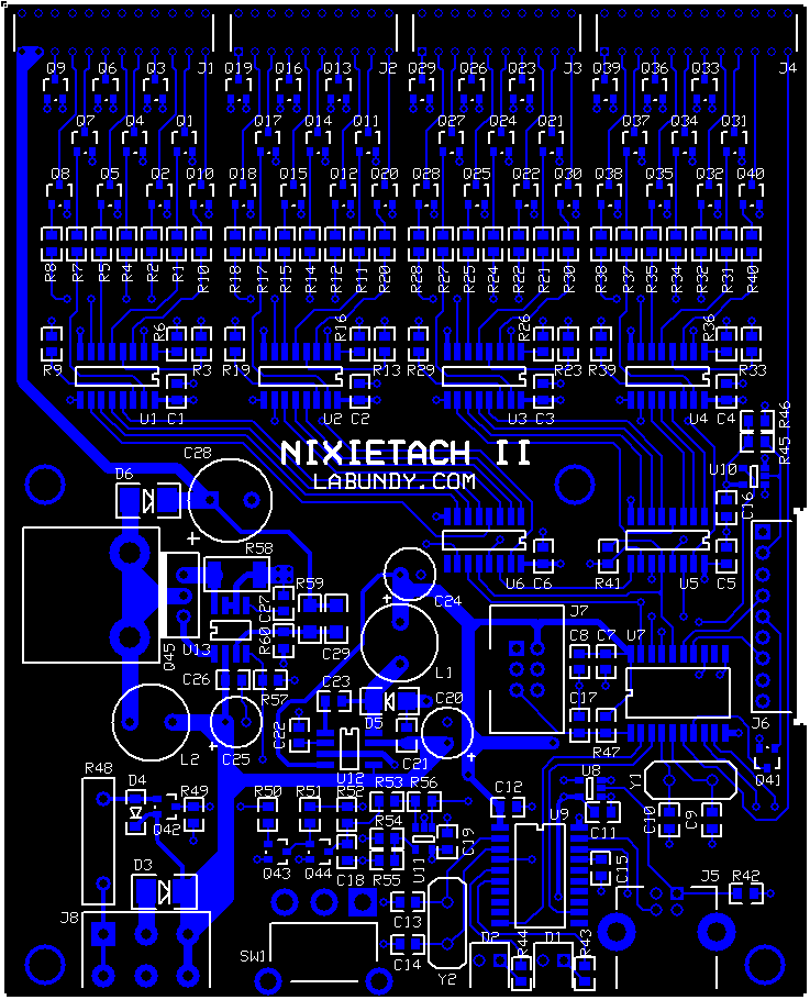
Figure 30: Main board PCB layout (top layer).
|
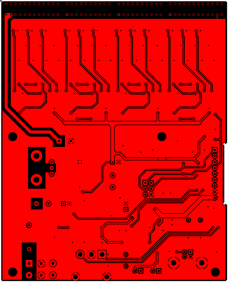
Figure 31: Main board PCB layout (bottom layer).
|
PCB Layout—Display Board
Click here to download in Gerber format.
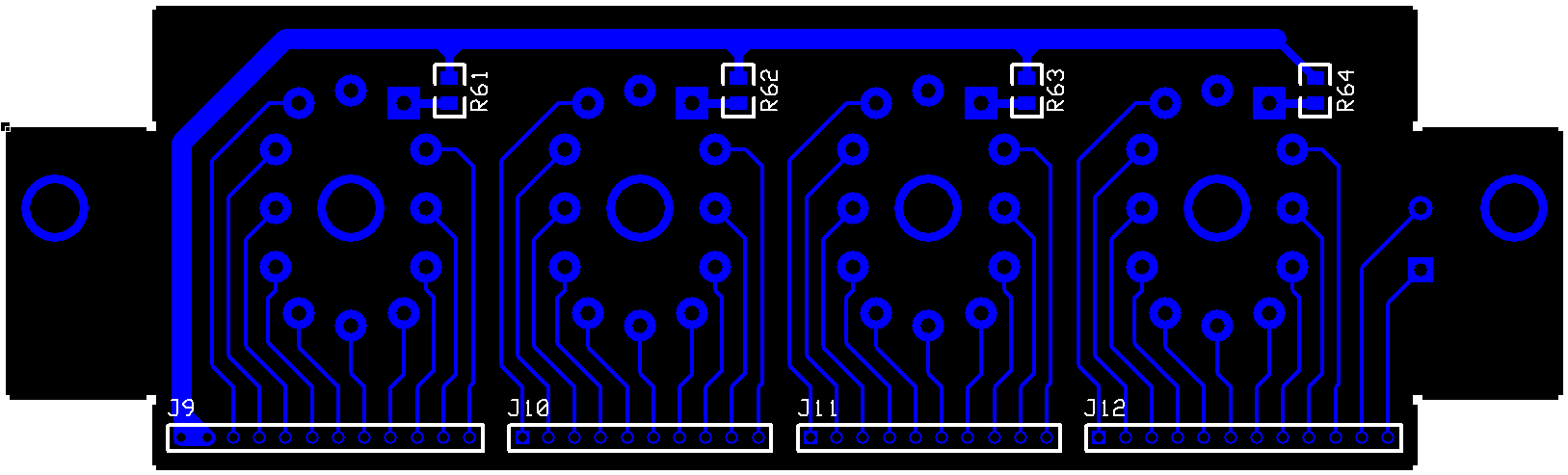
Figure 32: Display board PCB layout (top layer).
|
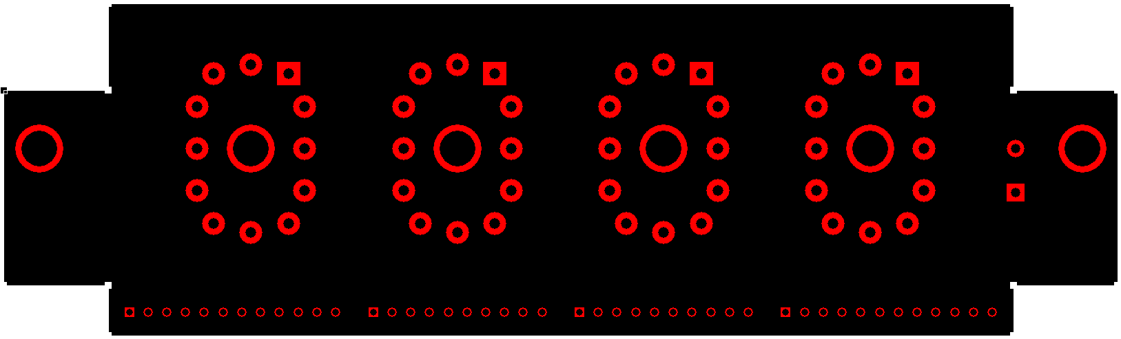
Figure 33: Display board PCB layout (bottom layer).
|
Miscellaneous Design Files
Enclosure Information
The six panels that comprise Nixietach II's enclosure are cut to size from sheets of ABS plastic or designed in Front Panel Express. Each piece of the enclosure is specified in the following table:
The top and bottom faces of the RPM/dwell switch (SW2) must be lightly sanded to make room for the M2.5 mounting nuts called out in the bill of materials. The switch is secured to the front panel from behind and connected to the display board with two cut-to-length pieces of 22-AWG wire.
|
|


