Nixietach
Introduction
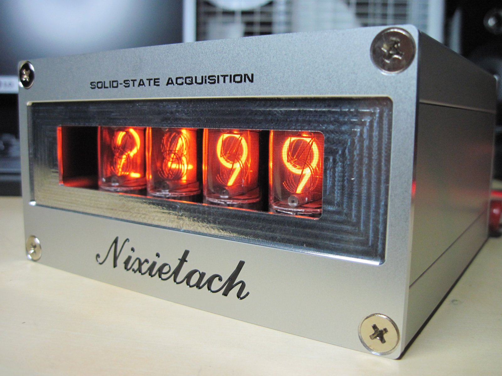
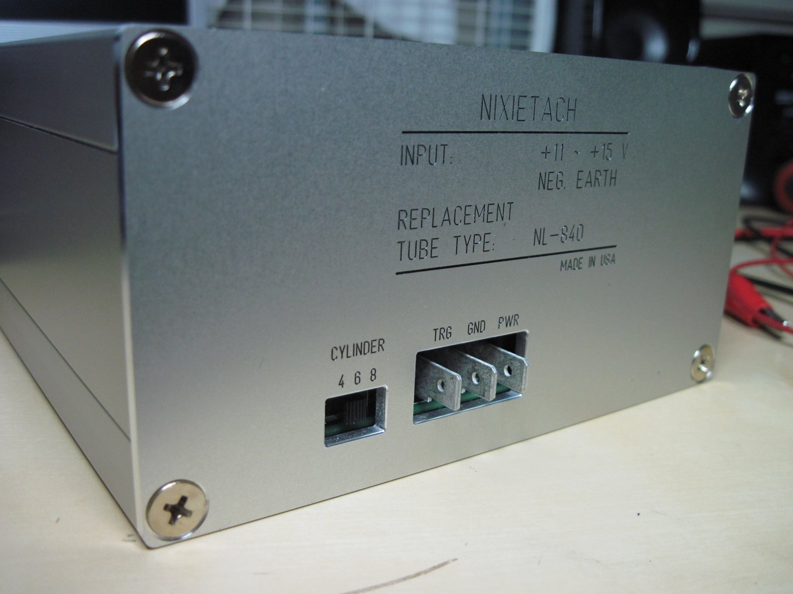
In late 2013, a fellow coworker gave me four 1968-model NL-840 Nixie tubes (most likely from a calculator), and challenged me to convert my original Digitach design to a Nixie tube version. Intrigued by their retro look and beautiful orange glow, I accepted the challenge—especially considering that such a design would be somewhat period correct for my 1979 Ford F100 pickup.
For this design, I stripped away the "thermometer" display and shift lights from the original version, and focused solely on a fixed-brightness four-digit display. I designed the enclosure completely in Front Panel Express, and tried to give it the vintage look of other equipment from the Nixie tube era. The Nixietach connects to the same trigger box as the original Digitach design and measures RPM using the same principle. I ultimately never installed this in my truck (which has since been sold), because I could never decide on a satisfactory mounting position given the design's size.
What Is A Nixie Tube?
Nixie tubes were among the first solid-state digital displays, ahead of seven-segment LED displays or mass use of vacuum-fluorescent displays. "Nixies" are similar in appearance to vacuum tubes and were popular in high-end desktop calculators as well as test and measurement equipment during the late 1960s and early 1970s. Nixie tubes are no longer manufactured and must be scavenged from used equipment or leftover service inventory.
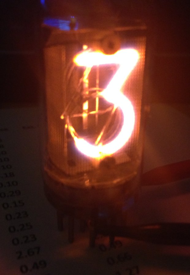
A single Nixie tube can create decimal numerals zero through nine (rare tubes can even create mathematical symbols or decimal points). Each numeral is constructed as a wire frame tied to a common anode. All ten wire frames are laid directly on top of one another with their individual cathodes exposed. By striking the anode with a relatively high "ionization" voltage (typically around 170 volts) and properly controlling the cathode current of a single numeral, the individual wire frame glows so brightly that the other nine numerals can't be seen. The illuminated numeral gives off a very beautiful, distinct orange glow.
The transistors used to ground each cathode must be rated to withstand relatively high voltages. During the height of the Nixie tube era, various manufacturers offered BCD decoders with integrated high-voltage BJTs to support Nixie tube designs. The vintage SN74141 from Texas Instruments and its Russian clones can often be spotted on eBay. Nixie tubes continue to remain popular with enthusiasts who most often use them in specialty timepieces.
Photos
|
Design Details
Aside from some minor optimizations to the firmware, the Nixietach operates in the same fashion as my previous Digitach project. However, the two designs use drastically different methods to display RPM. In the case of the Digitach, the seven-segment display is time division multiplexed such that all four digits share the same seven control signals. Each digit is individually enabled in rapid succession over a 250-ms period, giving the illusion that the entire display is illuminated at once—a convenience afforded by the fact that LEDs can be extinguished almost instantaneously.
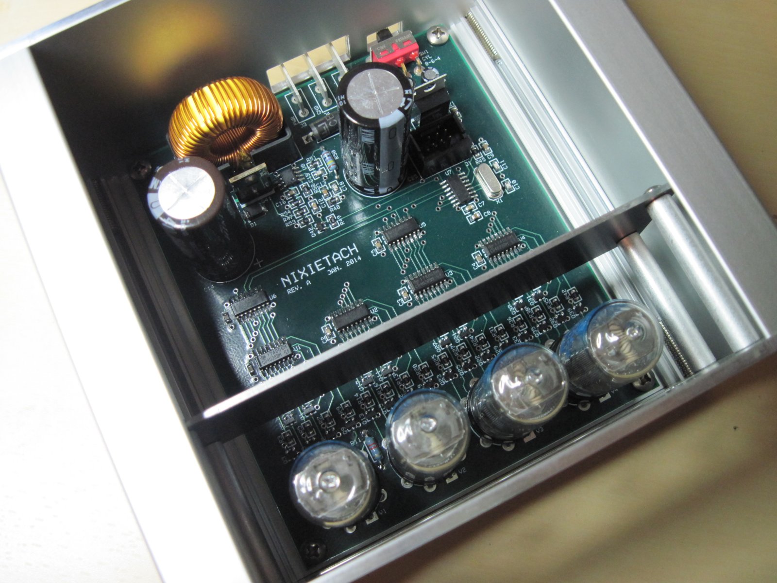
For this design, I was concerned that the same approach would penalize the high-voltage display with a flickering effect. To keep with the theme of limiting microcontroller pin count, I connected the ten control signals of each tube to one of four BCD decoders. I then connected all four BCD decoders to a pair of eight-bit shift registers driven by the microcontroller. Every 250 ms, the microcontroller "writes" a 16-bit value to the display using a serial data output, a clock output (strobe), and an enable output.
The Nixietach indicates if RPM is too low to measure by flashing a single zero on the right-most digit of the display. Individual digits can be blanked by driving a non-decimal number to the corresponding BCD decoder. For example—the three-digit decimal number 475 is represented by the microcontroller as hexadecimal 0xF475, which leaves the left-most digit completely blank. Conversely, the Digitach's seven-segment display indicates low RPM with the word OFF.
Schematic

Figure 4: Schematic page 1 of 4.
|
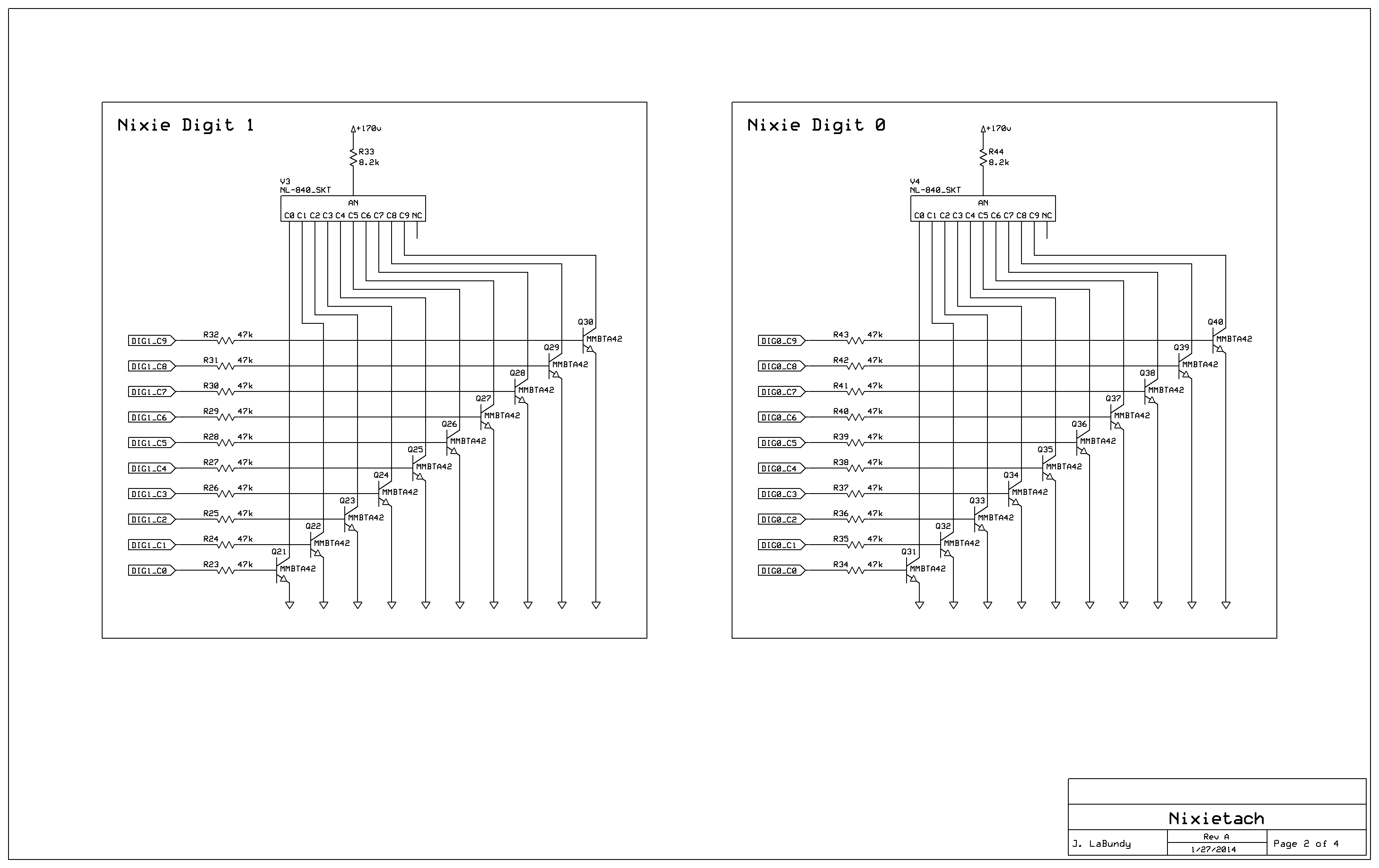
Figure 5: Schematic page 2 of 4.
|
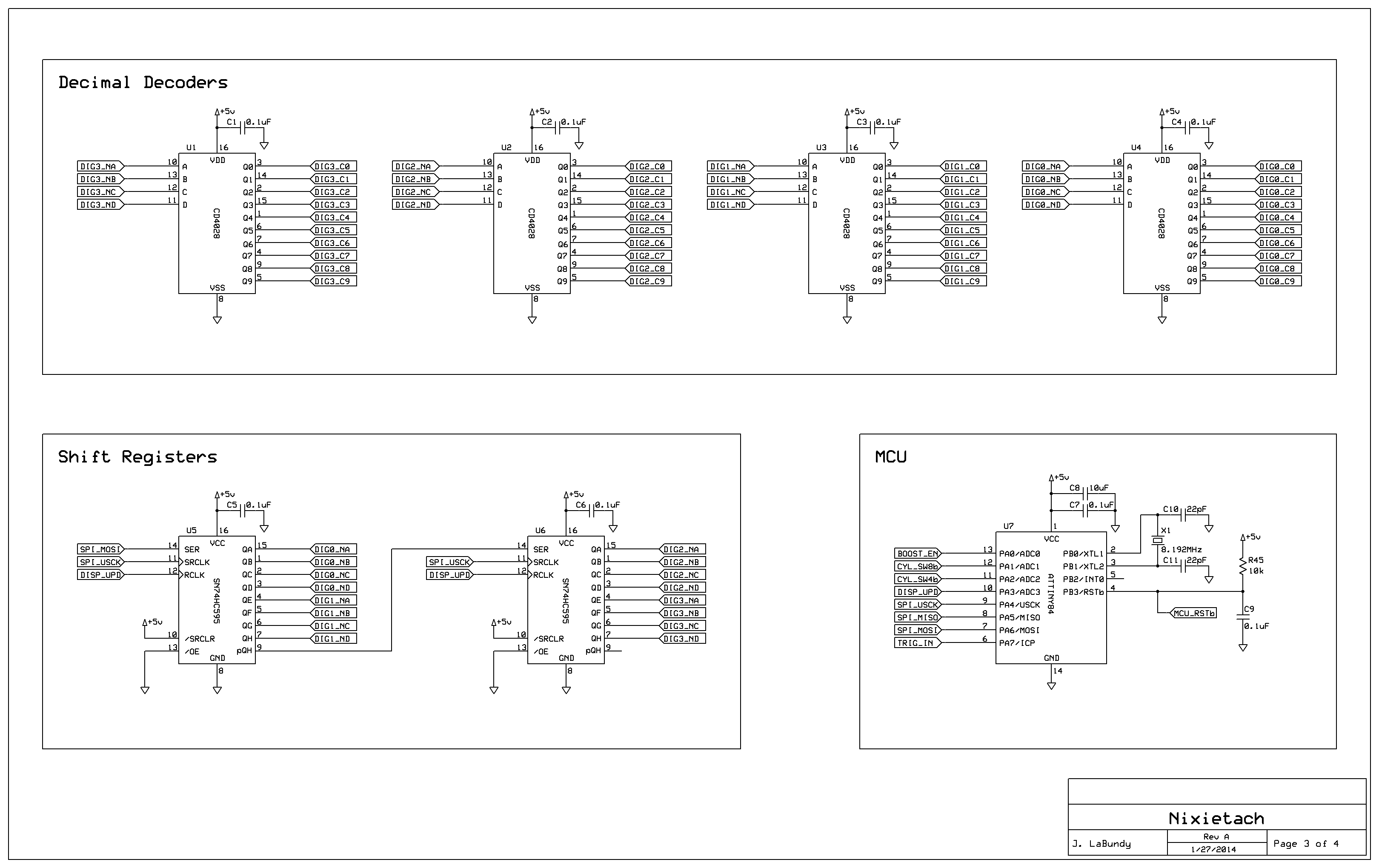
Figure 6: Schematic page 3 of 4.
|
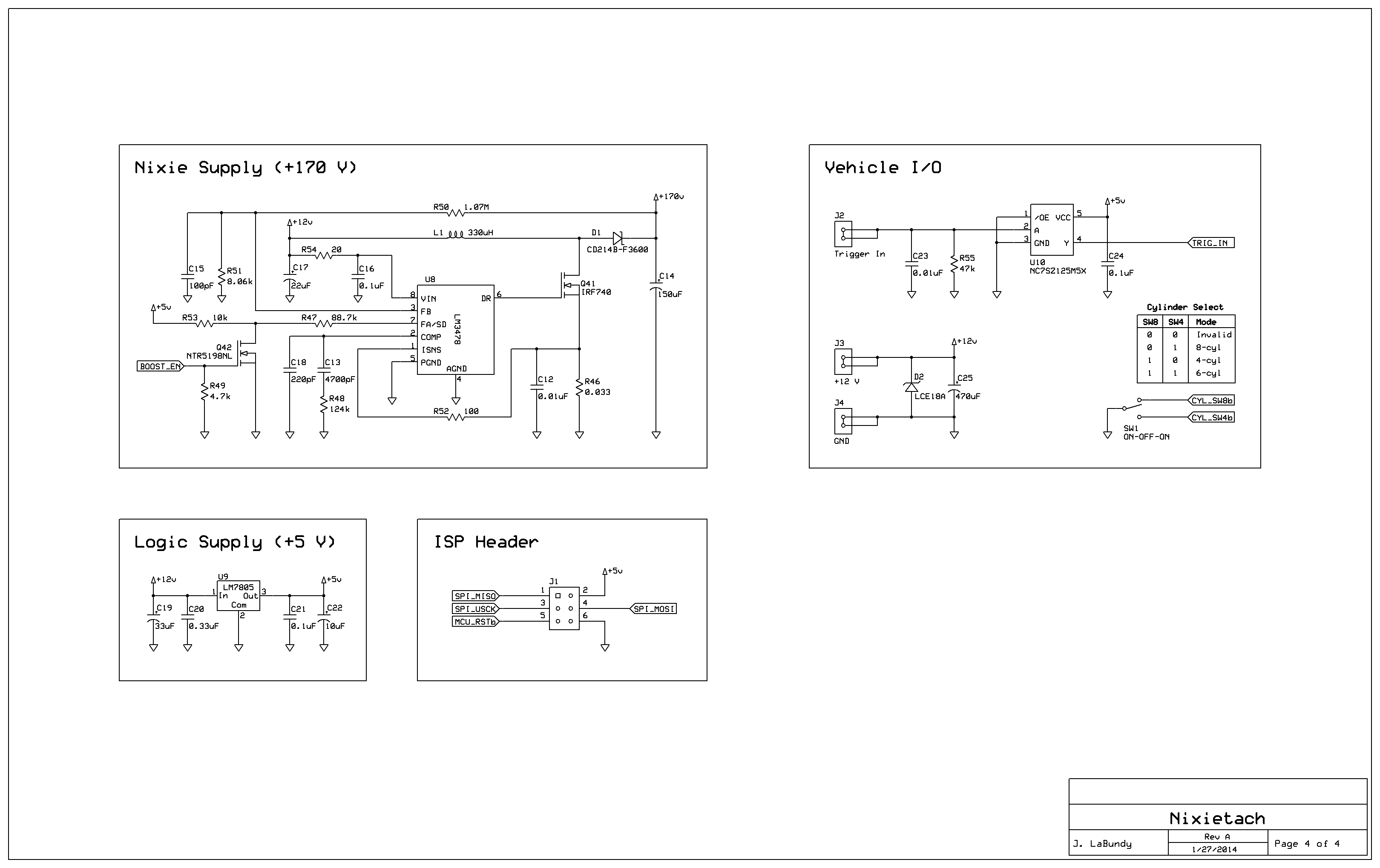
Figure 7: Schematic page 4 of 4.
|
PCB Layout
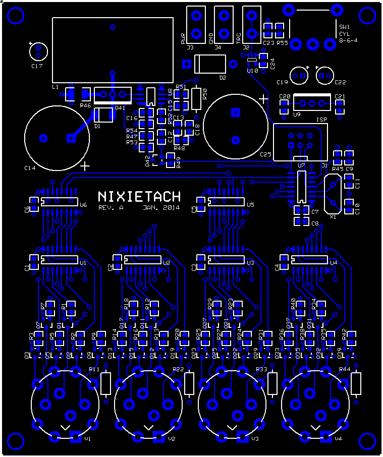
Figure 8: PCB layout (top layer).
|
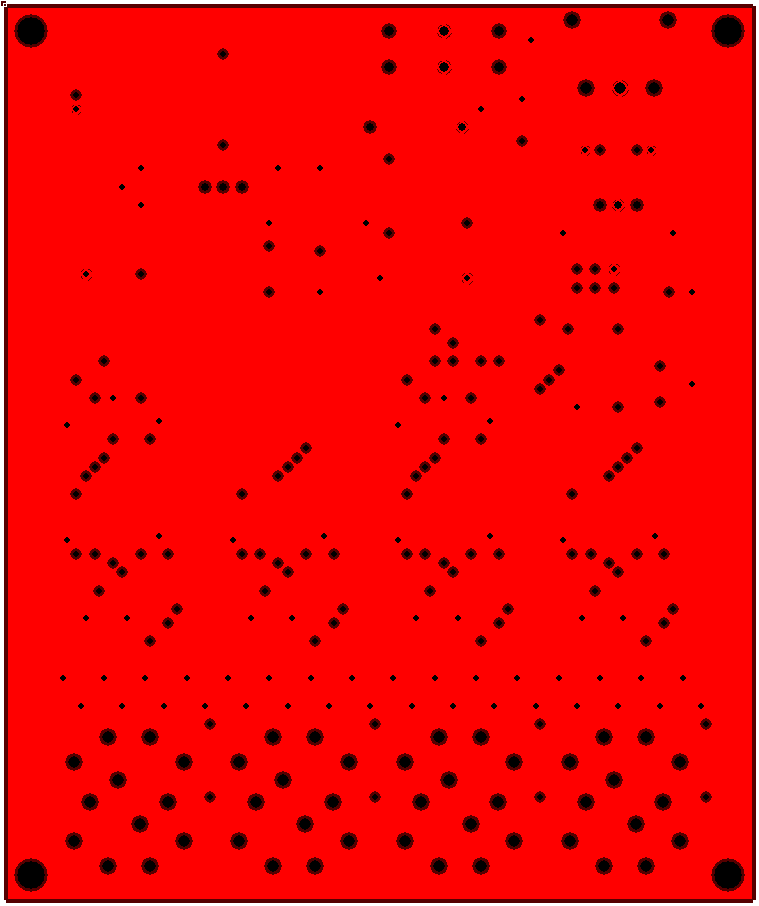
Figure 9: PCB layout (inner ground layer).
|
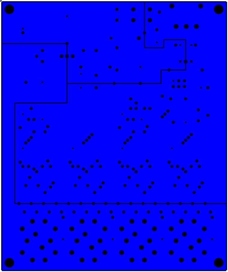
Figure 10: PCB layout (inner power layer).
|
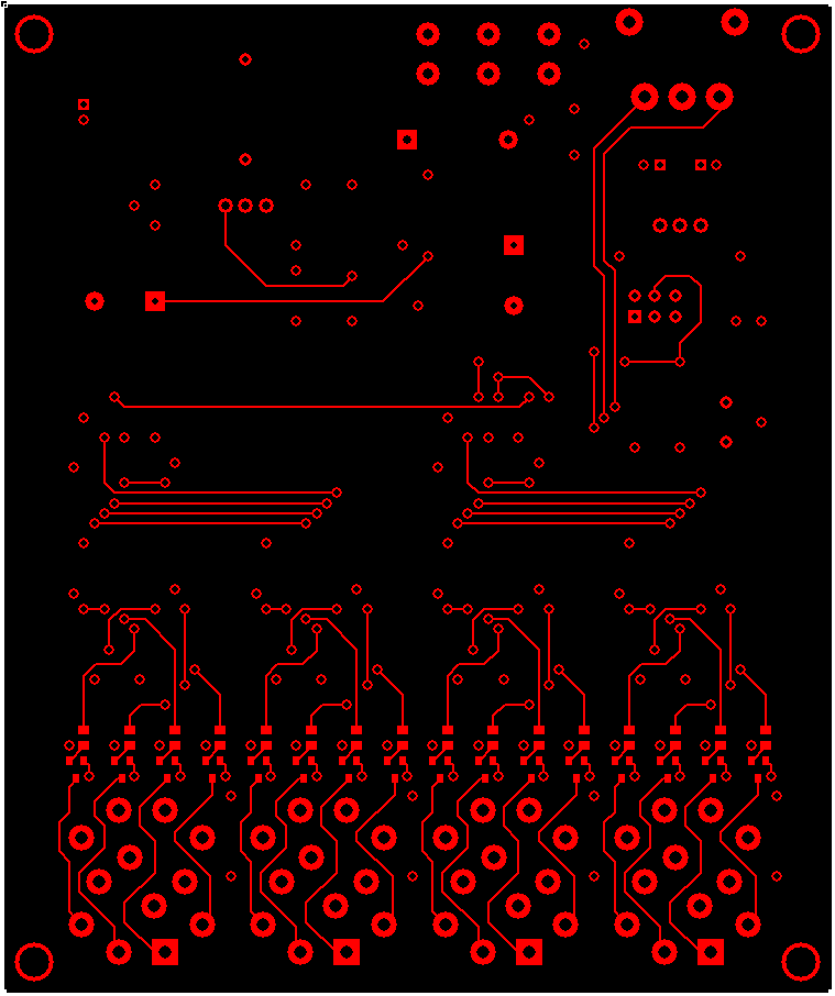
Figure 11: PCB layout (bottom layer).
|
Ideas for Improvement
For a second revision of this design, I would recommend the following changes:
- The Nixie tube sockets add unnecessary height to the enclosure and should be eliminated. Many Nixie tubes themselves can be hard to come across and their matching sockets are even harder to find. The sockets aren't useful because Nixie tubes seldom need to be replaced.
- My original intent was to drive the display with the microcontroller's native SPI peripheral, but I mistakenly connected the display input to the MOSI pin of the ISP interface (PA6) and not the data output (DO) pin of the SPI peripheral (PA5). Consequently, the present design "bit bangs" the display manually.
- The 470-μF input capacitor is excessive and should be reduced to help limit inrush current.
- I would reshuffle the microcontroller I/O to free one of the ADC0–3 pins, then connect a potentiometer and resistor to allow the driver to adjust the display update rate.
I addressed all but the last idea in a sequel, which I called Nixietach II.
|


