Background Information
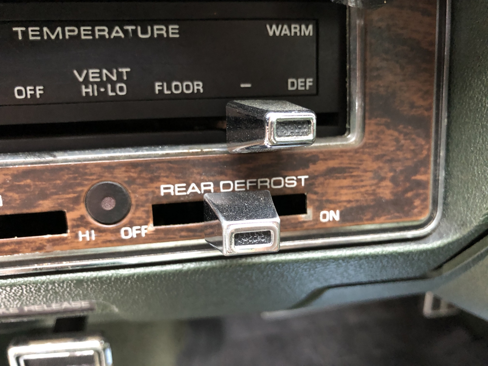
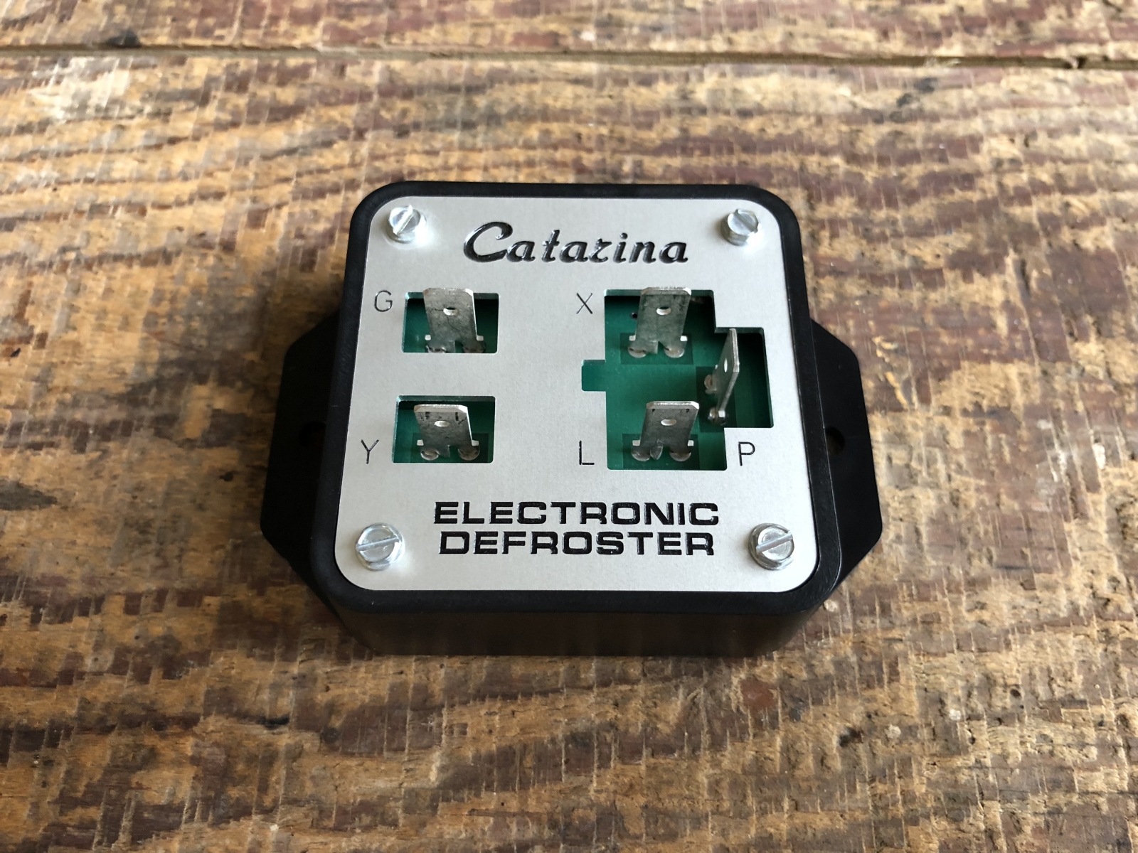
The factory relay has four terminals, labeled X, P, L and Y. The X terminal connects to the vehicle's battery, while the L terminal feeds the defroster as well as an indicator light to the left of the dash-mounted on/off switch. The on/off switch is a three-position momentary switch that returns to center after being released from the "on" or "off" positions. The P and Y terminals of the relay are selectively powered through the switch according to the following table:
| Switch Position |
P |
Y |
Action |
| On |
On |
On |
Turn on defroster and start timer |
| Center (resting) |
Off |
On |
Continue (keep running or stay off) |
| Off |
Off |
Off |
Turn off defroster and cancel timer |
The P and Y terminals are only powered if the vehicle's ignition switch rests in the 'run' or 'accessory' positions as a function of the key. The X terminal is powered at all times. Any power the relay needs for switching, timing, or state retention must come from the Y terminal to avoid drain on the vehicle's battery while the vehicle is not in use. The X terminal only serves as a direct power source for the defroster, and is shorted to the L terminal as a function of the relay's state. The P terminal starts the timer, and the timer is cancelled by disrupting power to the relay completely.
Five-Minute Timer
The LM555 is a popular means to implement a simple one-shot timer, but its usefulness is limited to short delays (typically under one minute). Long delays require the use of a large electrolytic capacitor to set the timer's delay. For a large enough capacitor, the capacitor's leakage current is on the same order of magnitude as the current used to charge the capacitor—and the accuracy of the timer suffers. Furthermore, the whole point of the new design was to avoid a large electrolytic capacitor in the first place.
A much better solution to implement a slow-moving timer is an HEF4060B 14-stage ripple-carry binary counter. This device generates a clock using an RC oscillator or a crystal, and uses that clock to increment a 14-bit counter. The higher-order bits of the counter are mapped to output pins, allowing the clock to be divided down by a factor as high as 214.
The HEF4060B makes for a useful counter, but it doesn't implement a complete one-shot timer because the counter simply rolls back to zero after reaching 214 − 1 = 16,383. There is no output from the counter to indicate state (counting or not counting), or to park the counter once a specific value is reached. However—if we pair the counter with an S/R latch like the HEF4043B as in Figure 7, we have everything we need to build a very slow one-shot timer.
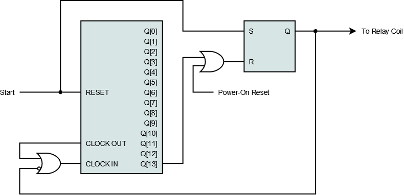
Figure 7: Logic diagram showing a one-shot timer built using a counter and an S/R latch. The power-on reset signal is explained later.
Here, the "start" signal (P input to the relay) drives both the reset input to the counter and the set input (S) of the S/R latch. The counter's most significant bit, Q[13], is its lowest-frequency output and drives the reset input (R) of the S/R latch. Pushing the defroster switch to "on" immediately sets the output of the S/R latch (Q), which in turn energizes the relay coil and powers the defroster. After the on/off switch returns to center, the counter is taken out of reset and begins incrementing from zero. When Q[13] is eventually asserted, the S/R latch is reset—simultaneously shutting off the defroster and freezing the counter by halting its clock.
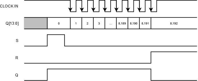
Figure 8: Timing diagram showing the clock input to the counter, outputs of the counter Q[13:0], inputs to the latch S and R, and output of the latch Q.
The period of the clock generated by the counter is set by an external resistor and capacitor, and is defined as follows:
tcounter = 2.3 × Rt × Ct
Where:
- tcounter = period of the clock generated by the counter, measured in seconds
- Rt = value of the external resistor, measured in Ω
- Ct = value of the external capacitor, measured in farads
If the counter starts from zero, it takes 213 = 8192 total tcounter periods for the counter's Q[13] output to reset the latch and shut off the defroster. In order for five minutes to pass before Q[13] is asserted, Rt and Ct must be chosen to satisfy the following equation:
5 × 60 = 8192 × 2.3 × Rt × Ct
Choosing Rt = 47 kΩ and Ct = 330 nF yields a nominal delay of 4 minutes and 52 seconds. Accounting for component tolerances (±5% for Rt and ±10% for Ct), the delay could vary from 4 minutes and 10 seconds to 5 minutes and 38 seconds—still tighter than the 3 to 7 minute range specified in Ford's 1971 service manual.
That's all fine and well once the driver starts the timer for the first time—but something must reset the S/R latch when power is applied to the Y terminal of the relay. This is important for two reasons—first, to ensure the defroster doesn't inadvertently turn on when the vehicle is started and power at the Y terminal first appears, and second, to guarantee the timer remains canceled after the driver releases the dash-mounted switch from the "off" position. Because the on/off switch cancels the timer by simply removing power from the Y terminal of the relay, we must design a power-on reset (POR) circuit to ensure that the relay doesn't pick up where it left off when the switch returns to center and power at the Y terminal reappears.
Power-On Reset
A common way to implement a POR circuit for digital logic is to make a low-pass filter using a single resistor and capacitor. In that case, the logic's reset input sees a low level for a brief period of time after the power supply is applied. While this approach is cheap and simple, it doesn't recognize brief disruptions in the power supply because the capacitor remains charged. For this design, the capacitor must be discharged immediately when the driver cancels the timer and the supply is removed.
For that to happen, we need something that conducts with no supply present—and a depletion-mode device such as a p-channel JFET is the answer. The Y input to the relay feeds the gate of the JFET; the gate is tied back to the JFET's source through resistor R1 as in Figure 9. Resistor R2 and capacitor C1 are placed in parallel with the source and drain, the latter of which is grounded.
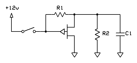
Figure 9: Capacitor C1 charges through resistors R1 and R2 when the switch is closed, but discharges through the JFET when the switch is opened.
When the switch is closed, C1 charges to the voltage divider set by R1 and R2—pulling the source of the JFET below the gate, holding the JFET off. C1 remains charged until the switch is opened, at which point the gate is pulled directly to the source by R1. With zero potential between the gate and the source, the JFET conducts and discharges C1 directly to ground. Figure 10 shows that C1 charges slowly when Y is applied, but discharges very quickly when Y is removed.
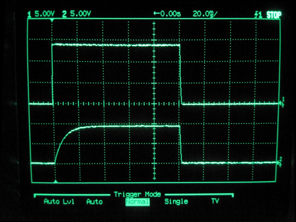
Figure 10: Oscilloscope capture showing removable Y input to relay (channel 1 at top) against voltage across capacitor C1 (channel 2 at bottom).
The voltage across C1 drives the inverting input of a comparator, which produces a brief logic-level pulse each time the Y input to the relay is applied and C1 begins to charge. The width of the pulse is controlled by the time constant of R1, R2 and C1—as well as the level of a DC reference that drives the non-inverting input of the comparator. This pulse represents the power-on reset signal in Figure 7, and ensures that the output (Q) of the S/R latch remains deasserted after the vehicle is first started or the driver cancels the timer.
Schematic
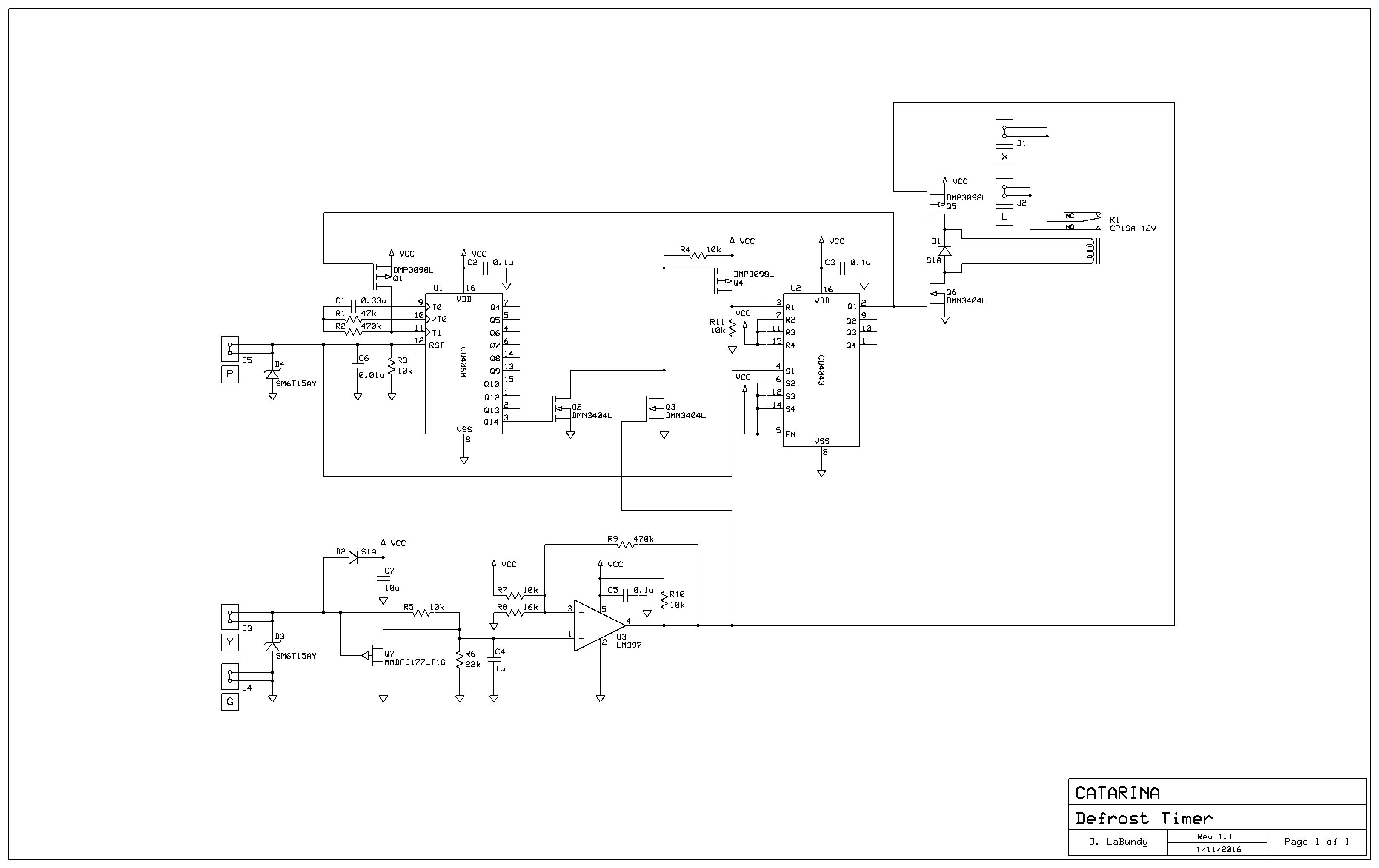
Figure 11: Schematic page 1 of 1.
PCB Layout
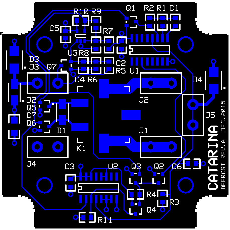
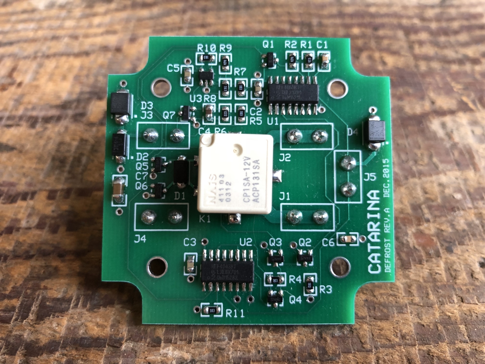
Figure 12: PCB layout (top layer).
|
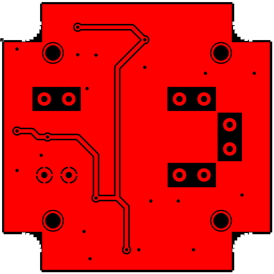
Figure 13: PCB layout (bottom layer).
|
Ideas for Improvement
Not long after completing the design, I realized that rear-window defrosters can easily draw up to 20 amps—meaning the traces to J1 and J2 in Figure 12 are undersized. For a future revision, I would grow these traces into much larger copper pours. For the existing revision, the problem can be solved by soldering some short lengths of 16-AWG wire in parallel with the undersized traces.
Unfortunately, the defroster in my LTD seems to draw barely any current and does little to clear the rear window of moisture. A layer of window tint across the heating elements makes the problem somewhat difficult to troubleshoot. As such, there isn't much use in updating the design and I haven't actually installed it.
|


